The motion of a robot inside a field with obstacles
Line follower
To solve the problem of robot motion inside a field with obstacles, two different philosophies can be followed. The first is to trace a predefined path to avoid obstacles, in case you know beforehand the object to avoid, the second is to probe the surrounding space through appropriate sensors and to define the better path that allows the robot to avoid the obstacles. These two different philosophies lead to two different methodologies:
Line follower
Interpolated curves.
In this paper we will analyze the two different methodologies, limiting ourself in the second case to the study of simple models within the reach of upper secondary school students.
Introduction
We propose a project of educational robotics for upper secondary school.The activity has been experimented in the scholastic field during the 2017/2018 academic year. To pursue a line is one of the typical problems of control theory: it means to obtain a desired behavior from a system (the robot) that follows a certain reference (a line). But why should a robot follow a line? Surely because in this way it could be made to move with a certain security within a space, without having to resort to other engineering concepts
Some examples from the real world of robots that work by exploiting this solution:
- Restaurants
- Industrial world
- World health care
The proposed activity has been tested with the fourth classes of the our institute Erasmo da Rotterdam Nichelino – (To) Italy
Prerequisite
What students should know before
Basic knowledge of the LEGO® Mindstorms EV3 Education kit , light and color sensor.
Basic knowledge of the LEGO® Mindstorms EV3 Home Edition Software.
Basic knowledge of Python.
Time constraints: 12 hrs.
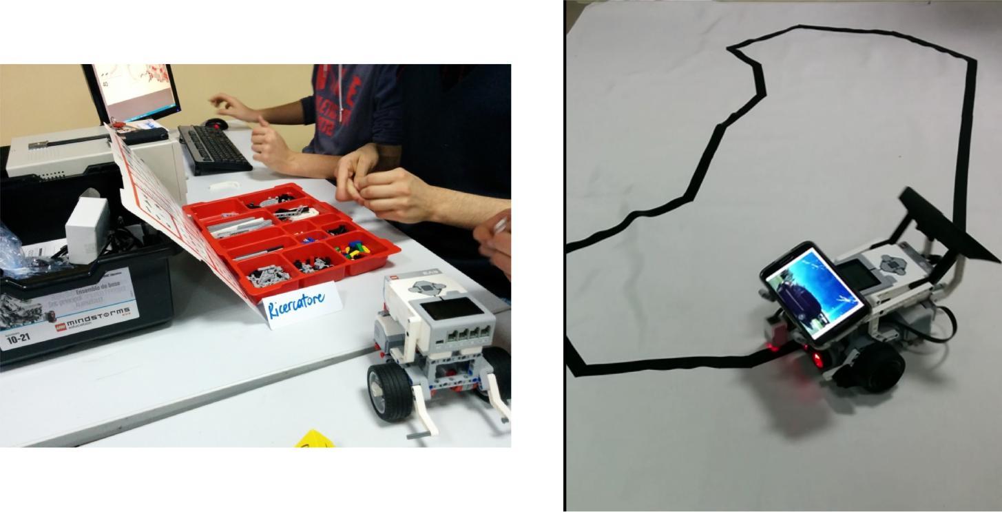
Preparing For This Tutorial:
- Instruments
Computers.
LEGO® Mindstorms EV3 Education Kit.
LEGO® Mindstorms EV3 Home Edition software and Python.
A white sheet on which a path is prepared using, for example, 2 and 5 cm black insulation tapes. Remember that the more tight the curves, the more complex it will be to program the robot and find suitable algorithms for tracking the line.
Methodology
The methodology adopted for the realization of the project was that of learning based on problem solving and learning: “challenge-based”. At the beginning of each lesson a problem or challenge was proposed that the students have to solve by working in a team; which also involves collaborative learning among the strategies chosen during the design phase of the activity.
Effects
Exercise
Example solution
Part 1
The first two meeting
Part 2
If we know that the robot is positioned on a white area, and must arrive on the black and stop the algorithm could be of this type:
#(the initial values will be high -> the robot is on the white)
Part 3
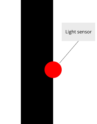
The fourth meeting It is the moment when students started “banging their heads” against the main problem. Try to chase the line! Here it is always very interesting to leave time for the students to construct an algorithm hypothesis in total freedom, without influencing their choices and experiments. They will certainly ask for tips and advice. The support from the teacher could come in the form of questions: if we start from the hypothesis that the robot is above the black line, what is the desired value, what the robot would like to measure continuously (with the sensor light) during its operation? The most obvious answer is the value of black, because this would mean that the robot during all its operation would always be perfectly above the black line. From which other ideas can be born. But if the robot is precisely located with the sensor above the line, and at some point the value of reflected light detected by the sensor increases, which way do I bend the robot to correct the position and return to black? Right or left? | My be in some cases the value would increase in the same way in both directions, so it would not be possible to set a resolutive algorithm starting from this idea. We could never know what curve to impose on the robot to correct the position and return to the center of the black line! Need an alternative solution! At this point the students can work looking for a different value to follow, the “pure” black we do not like anymore. | At this stage it is essential to give them time to experiment in search of an alternative and effective solution. | The solution that we propose is to choose as desired value 50% of white and 50% of black (typical ideal situation with white = 100 and black = 0 among which we average obtaining the value 50), with the sensor positioned on the right end of the belt, This solution is called ON-OFF because the robot either turns to the right or left, always with the same curvature parameters.There are no other possibilities!
to measure these two values and then calculate the real average value between the two, before constructing the algorithm. In the scheme as average value is found 38.5 because in real conditions (in which there are variables to take into account as ambient light, the cloth of a not perfect white color), we will never have as values: | - Light reflected on black = 0 | - Light reflected on white = 100
See Appendix 1 Line follower code ON - OF
Part 4
The fifth meeting
You could start with this challenge: Improve the control algorithm! Can the robot avoid (or decrease) this oscillation? You can ask the students what is due, and why the robot behaves in this way (always leaving time to reflect, hypothesize and experiment). The robot oscillates because the ON-OFF algorithm provides only 2 states, independent of the value detected by the sensor: turn right or turn left, always the same amount! But the values found could be infinite, and therefore the corrections to be applied to the robot can become of order “infinite”. The correction i.e., should be proportional to the error that the robot is committing! A further sensor on the left edge can be inserted in the same way as the right sensor. In this case the speed of the two motors can be calibrated in a way directly proportional to the brightness of the two sensors.
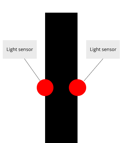
If the brightness of the right sensor is reduced, reduce the speed of the right motor proportionally, if the brightness of the left sensor is increased, increase proportionally the speed of the left motor, if the brightness is equal, proceed with the same speed of the two motors. Another way to control the movement of the robot is to introduce a control on the system that assesses the error compared to the optimum trajectory. The error indicated with E is nothing more than the difference between the value acquired by the sensor and the desired value (average between white and black). The correction of the robot (i.e. how much steer should be proportional to this error where Kp represents the coefficient of proportionality and is to be found empirically, it should be found by students. Depends on the speed at which the robot moves, how thick the line of the path, the white tone of the cloth, the light in the room. In short, students will have to “fiddle” a little ‘ to find the right value for this constant, which should be between 0.5 and 3 (in the case of a project of this type). It would be interesting to document the behavior of the robot according to the different Kp assigned. To find the best value it is worth advising students to initially set 1, and then proceed to modify about 0.2 the constant, until you get to the value that convinces them the most.
feedback and the difference between a robot that moves in a known environment, exploiting known mathematical relationships, and their robot that moves using the sensor information. If I knew the circumference of the robot wheel, and wanted to make it go forward by 2 meters, I could calculate how many wheel revolutions it takes to cover this distance. Same if I had the exact speed and acceleration of the robot: I could take advantage of physical relationships to get the desired behavior
See Appendix 2.
Part 5
The last meeting
For the sixth and final meeting, a challenge has been proposed that the students have solved by reconfiguring the elements seen up to this point. They have been asked to move an object within a security area or warehouse (as if they were to program an industrial robot) in the shortest time possible.
With students of the fifth superior, two other topics could be addressed:
Meeting 7-Proportional derivative algorithm (PD Controller) ( 6 h )
Encounter 8-Integrative derivative proportional algorithm (PID Controller) ( 6 h )
derivative and integrative action, so as to obtain one of the most famous control strategies: the PID, in attachment you will find an algorithm of the line follower, its experimentation will be carried out next year when the students will acquire the basic skills in the differential and integral calculus.
See Appendix 3
Summary
Appendix 1
Line follower code ON - OF
#!/usr/bin/env python3

function CALIBRATE

print "WHITE?"

#Wait for Touch Sensor to change

white = Read Light Sensor

print "BLACK?"

#Wait for Touch Sensor to change

black = Read Light Sensor

done function

program LINE FOLLOWING

white = 0, black = 0

CALIBRATE()

midpoint = ( white - black ) / 2 + black

repeat

value = Read Light Sensor

if value < midpoint then

  motor B set power 50

  motor C set power 25

else

  motor B set power 25

  motor C set power 50

done if

done repeat

done program
Appendix 2
Line Follower with P controller
program LINE FOLLOWER
#!/usr/bin/env python3

white = 0, black = 0

CALIBRATE()

midpoint = ( white - black ) / 2 + black

kp = 1, ki = 1, kd = 1

lasterror=0

repeat

value = Read Light Sensor

error = midpoint - value

integral = error + integral

derivative = error - lasterror

correction = kp \* error + ki \* integral + kd \* derivative

#Turn B+C Motors by correction

lasterror = error

done repeat

done program
Appendix 3
Line Follower with PID controller
program LINE FOLLOWER
#!/usr/bin/env python3

white = 0, black = 0

CALIBRATE()

midpoint = ( white - black ) / 2 + black

kp = 1, ki = 1, kd = 1

lasterror=0

repeat

value = Read Light Sensor

error = midpoint - value

integral = error + integral

derivative = error - lasterror

correction = kp \* error + ki \* integral + kd \* derivative

#Turn B+C Motors by correction

lasterror = error

done repeat

done program